Wiring Diagram For A One Wire Alternator
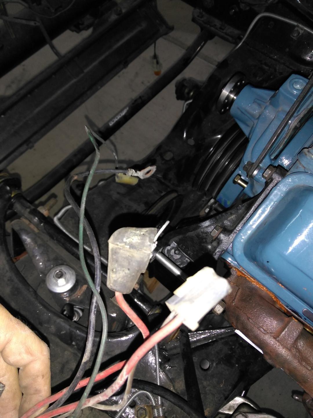
Wiring diagram gauge volt wire amp. And connect the red wire to the output side of the alternator 10/32 stud, take the long wire and connect to the + side of the coil.
One Wire Alternator Warning Light YouTube
A 3 wire alternator wiring diagram has three wires:
Wiring diagram for a one wire alternator. The 3 wire alternator wiring diagram is considerably less intrusive than it seems, as only two additional wires are integrated into the rest of the electrical system. And we are going to help you out when it comes to this. 120v single phase, 3 wires (one hot wire + neutral wire + ground wire) 208v single phase, 3 wires (one hot wire from high leg delta + neutral wire + ground wire) 240v single phase, 3 wires (two out of phase hot wires + ground wire) 240v three phase, 4 wires (three out of phase hot wires (one is high leg delta) + ground wire)
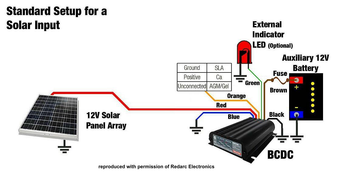
Here's a simplified wiring diagram of the alternator circuit for the 1992 2.3l ford ranger. This wiring diagram is for rv's with factory 30a shore power and will show you what you need to install up to 1200w solar and a 3000w inverter to your existing electrical system. This is why you need to know this stuff.
Does it check the vehicle’s voltage internally or from an outside source? Wire sizes on these and most other wiring diagrams are printed on the wire in mm 2.for americans who express wire sizes in gauges, see this wire size conversion table. The 4 pin trailer wiring diagram is the most essential thing that you will need to understand.
One thing to note, is that the 12 gauge inline. Battery positive cable, voltage sensing wire, and ignition wire. You will likely have a wire charging your oem batteries.
And also the 4 pin to 7 pin trailer adapter wiring diagram. Sir one more question, your diagram does not specify what to do with the main phase wire for e.g. Automatic ups system wiring circuit diagram for home or office (new design with one live wire) automatic ups system wiring diagram in case of some items depends on ups and rest depends on main power at office or home.
Ford 8n 12 volt conversion wiring diagram — untpikapps www.untpikapps.com. Gm has many different alternators and each has its own alternator wiring diagram and alternator symptoms. The pdf shown here is for a gm.
Diagrams 8n shay ammeter harness 1494 schematics distributor 2020cadillac chev untpikapps stromlaufplan firing alternator schaltplan [hy_8298] 12 volt amp gauge wiring diagram free diagram inst.unec.hendil.mohammedshrine.org. Manual ups wiring diagram with change over switch system. Automatic ups system wiring circuit diagram for home or office;
The red wire goes to the battery, the yellow wire goes to the idiot light, and the white/red stripe wire goes to the alternator’s power terminal. Most modules use an internal driver to turn the alternator’s field circuit on. Since most cars are running 7 pin connections at the rear end.
Although the yellow wire is optional, it should always have a voltage of at least 12 volts when the ignition switch is in the on position. This article includes the following subtopics: See that you have everything you're supposed to have in this kit.
One of the key differences is how the internal voltage regulator determines charge rate. In 1898, the french company renault, specializing in the manufacture of automobiles, was founded.the brand was founded by the. If i connect a fan switch to the ups, the ups wire is connected to the switch, but what do i do with the existing wapda phase wire that was connected to the.
You will find excellent wiring diagrams for all makes, years and models of vws at vw wiring diagrams. The second wire (green) to originate from the connector is responsible for the right signal. The third (brown) wire is the one that is responsible for the taillights.
One of these wires is also likely the wire coming from the alternator to charge the house battery bank. 3 wire alternator wiring diagram source: Fig 5 shows the same connection to control a light point from three places by using different symbols.
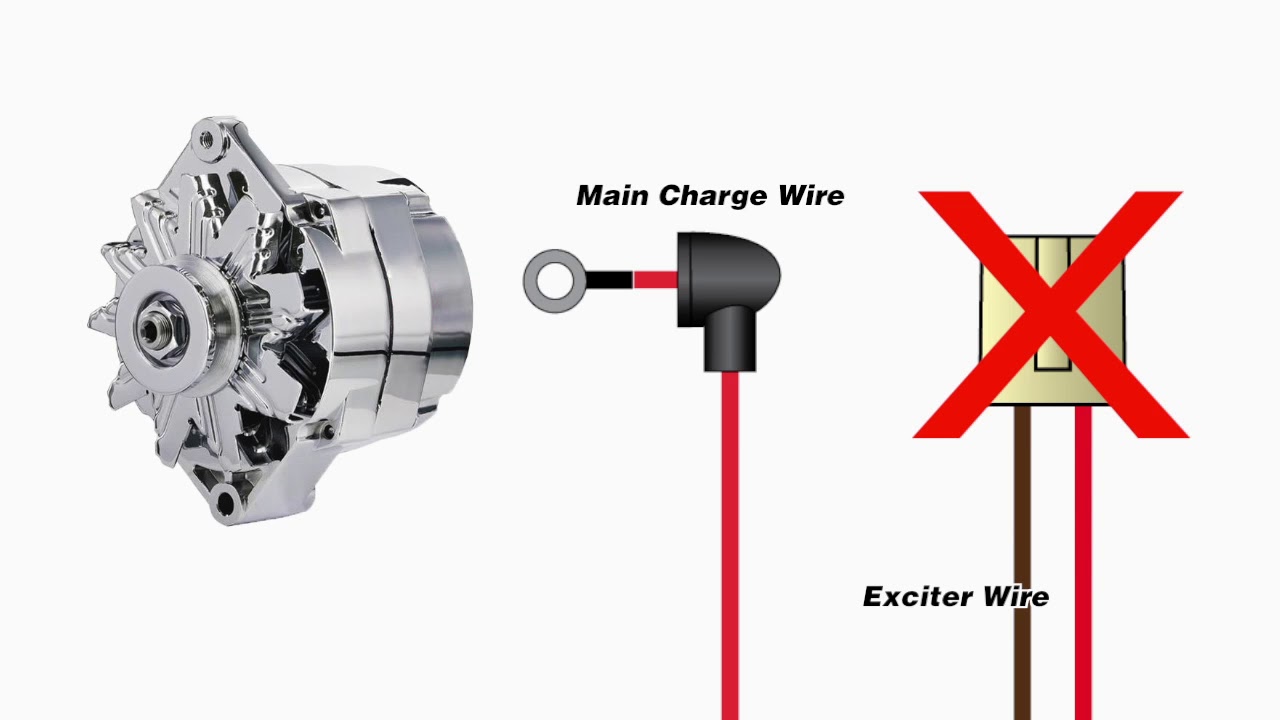
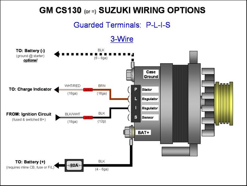
The primary charge wire, a third wire that can jump between the regulator and the battery stud, and the exciter wire. It is a type of polyphase system employing three wires (or four including an optional neutral return wire) and is the most common method used by electrical grids worldwide to transfer power. (battery bank wiring section has enough lugs wire & heat shrink for up to 4 individual batteries).
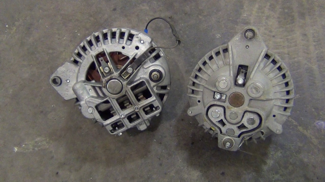
Gm alternator wiring gm alternator wiring. Testing the alternator, to see if it's charging or not is a pretty simple test, especially of you have a wiring diagram! The circuit comprises three main wires:
These are also connected to the side to ensure increased visibility.
Help with alternator wires 1979 CorvetteForum Chevrolet Corvette Forum Discussion
Pajero Alternator Wiring Diagram

» GM CS130/CS144 Alternator Wiring (PLIS) 3Wire GM Alternator Diagrams GM CS130/CS144
Rob installs a Redarc BCDC1225 charger
While replacing the alternator on my 2002 gs300, the wires came out of the wire connector to the

S13 alternator wiring question Nissan Forum Nissan Forums
Classic Mopar High Amp Alternator Wiring Upgrade YouTube