Wiring Diagram Of Motor
A wiring diagram is a simple visual representation in the physical connections and physical layout of your electrical system or circuit. 240v motor wiring diagram single phase source:
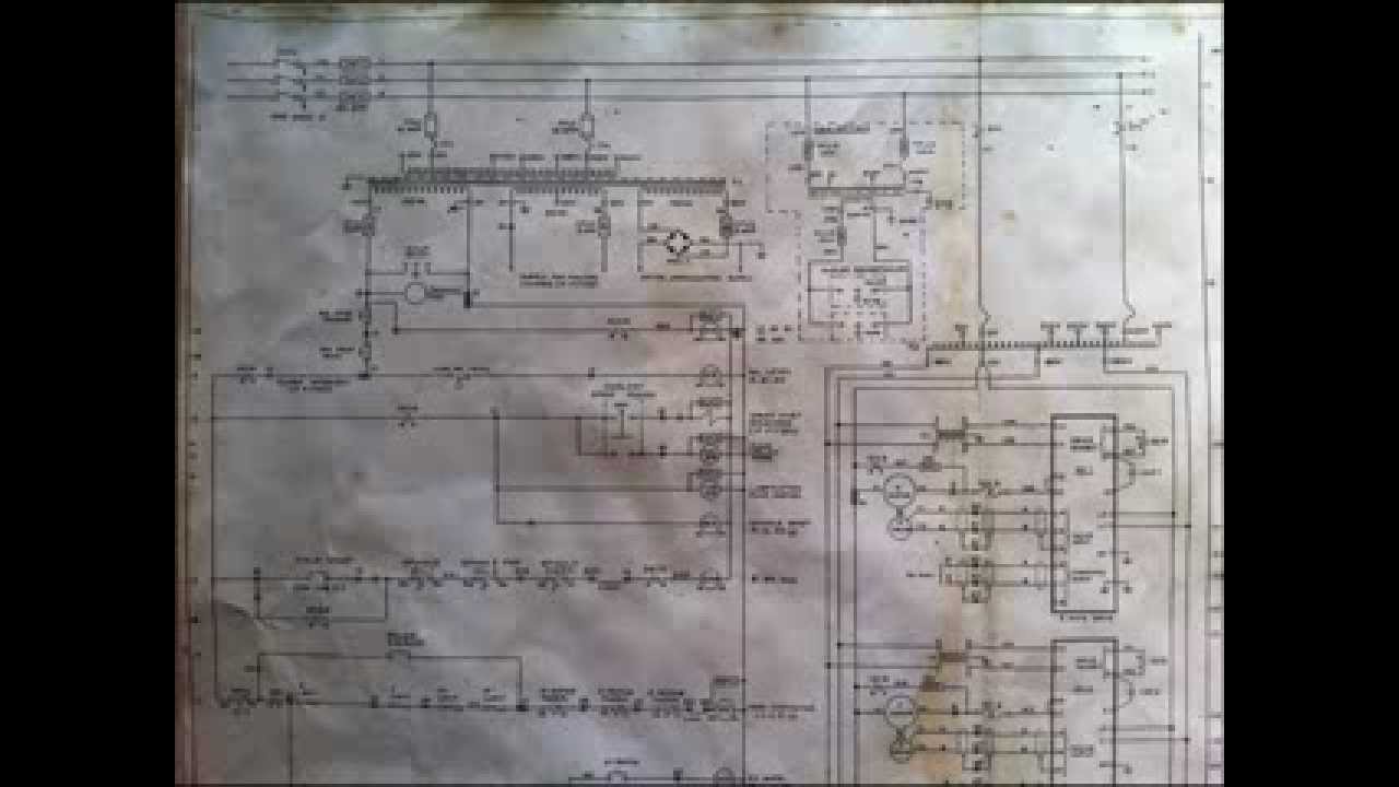
Bridgeport Interact 1 Mk2 Schemetic wiring diagram YouTube
Single phase motor overload protection.

Wiring diagram of motor. 75121 room unit air conditioner wiring diagram sears roebuck window air conditioner wiring diagram for a typical room or window air conditioner Ac65, ac80, ac90, ac100 three phase motors; I won’t to install a console with steering wheel and throttle controler.
If you don't have a battery load tester to test the battery at least depress the test button on the battery charger to check the. Essential tips for safe electrical repairs When and how to use a wiring diagram
Howard st., niles il 60714 usa, retrieved 2017/07/09, original source: Motor verso is an automotive website; All circuits are usually the same :.
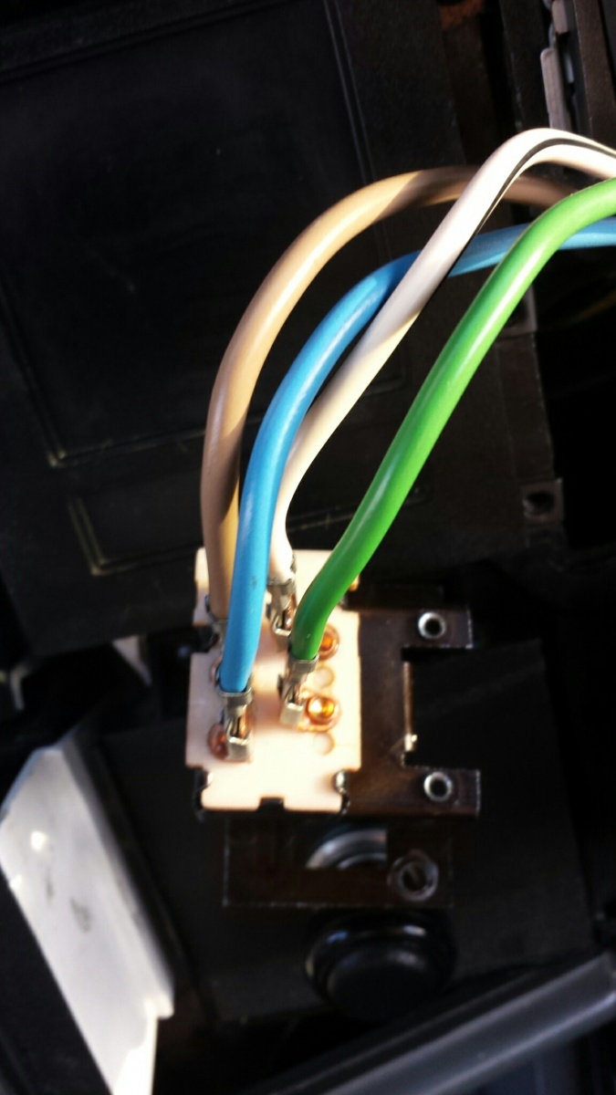
4) after pulling all four wires through the conduit and into the equipment control box, connect them to the proper terminals as indicated by the wiring diagram on the lid of the equipment control box. Motor 3ct to 120 v separate control * ot is a switch that opens when an overtemperature condition exists (type mfo and mgo only) t1 t3 motor 3 2 l2 t2. We have a focus on strong photography, and engaging articles about performance, luxury and interesting.
Ac80, ac90, ac100 single phase motors; The 4 pin trailer wiring diagram is the most essential thing that you will need to understand. 4 wire reversible psc motor;
The mg996r is a metal gear servo motor with a maximum stall torque of 11 kg/cm. For any maintenance and repairs in the system, schematic diagrams are the. Like other rc servos the motor rotates from 0 to 180 degree based on the duty cycle of the pwm wave supplied to its signal pin.
A wiring diagram is mainly used in motor control installations and designing electrical circuits. Before you start testing the wiring and controls make sure your dump trailers battery is charged to at least 12 volts dc. However, before getting to work, we recommend you the following essential tips for installing an rv.
You will find excellent wiring diagrams for all makes, years and models of vws at vw wiring diagrams. Wire sizes on these and most other wiring diagrams are printed on the wire in mm 2.for americans who express wire sizes in gauges, see this wire size conversion table. For car enthusiasts, run by car enthusiasts.
And also the 4 pin to 7 pin trailer adapter wiring diagram. The pump motor has lost its ground or the pump motor itself is bad. Click here for 727 to 46rh swap wiring diagram pa 727518 quantity add to cart sku:
The common elements in a wiring diagram are ground, power supply, wire and connection, output devices, switches, resistors, logic gate, lights, etc. 4 wire reversible psc motor with a triple pole double throw switch; Mg996r servo motor wiring diagram.
Wiring diagram book a1 15 b1 b2 16 18 b3 a2 b1 b3 15 supply voltage 16 18 l m h 2 levels b2 l1 f u 1 460 v f u 2 l2 l3 gnd h1 h3 h2 h4 f u 3 x1a f u 4 f u 5 x2a r power on optional x1 x2115 v. 5) configure the jumpers to the correct position as indicated by the wiring diagram on the lid of the equipment control box. Previously, we discussed what a magnetic motor starter is (a contactor and an overload relay).
I have a tracker 2016 1448mvx with a 2016 25hp efi mucury motor with tiller drive. The basic washing machine motor wiring diagram is called direct drive if is connected to ac direct wire or hot wire washing machine motor is very easy just follow the wires and starting from bottom 1+3 stay connected and the rest 2 and 4 we gonna connect them to battery or ac source the connection is the same because is a universal motor it can. Wiring diagram ws= white sw = black ro = red br = brown gn = green bl = blue gr = grey li = lilac ge = yellow vehicle electrical system control module, steering column electronic systems control module, windshield wiper motor, washer pump or = orange rs = pink audi a4 no.
Ac80, ac90, ac100 single phase motors; This article includes the following subtopics: I will continue to start the motor with the starter button on the motor.
A schematic diagram is mostly used in the electrical industry. It shows how the electrical wires are interconnected and may also show where fixtures and components could possibly be connected to the system. Below you will find the most standard rv inverter wiring diagram.
It shows how the electrical wires are interconnected and can also show where fixtures and components may be connected to the system. In this article, we give you an rv inverter wiring diagram, we explain how to instal an rv inverter and help you choose the best one for your needs. Use this as a reference when working on your boat wiring.
Dayton electric motor wiring diagram [pdf], dayton electric mfg. It visually represents the outline for all physical components of the system and their respective positions. For more information on wiring batteries, please review the conductor gauge and circuit breaker sizing table on our trolling motor wiring and battery guide.
3 wire, 3 phase motor; The overload relay is designed so the current to the motor is. 46re / 46rh , 727 , dodge , newyear2020 , save5 tags:
Wiring color diagram for tracker and bass tracker boats. A wiring diagram is a simple visual representation of the physical connections and physical layout of an electrical system or circuit.
Need Help with bench top milling machine with 110/220 wiring

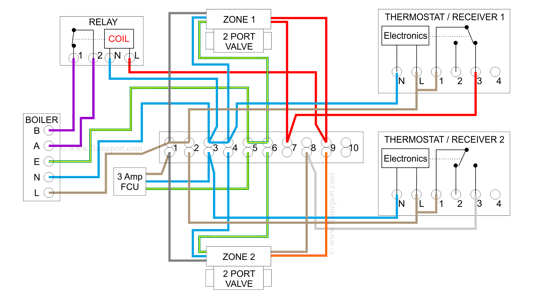
Combination Boiler with 2 Heating Zones, Relay Switching
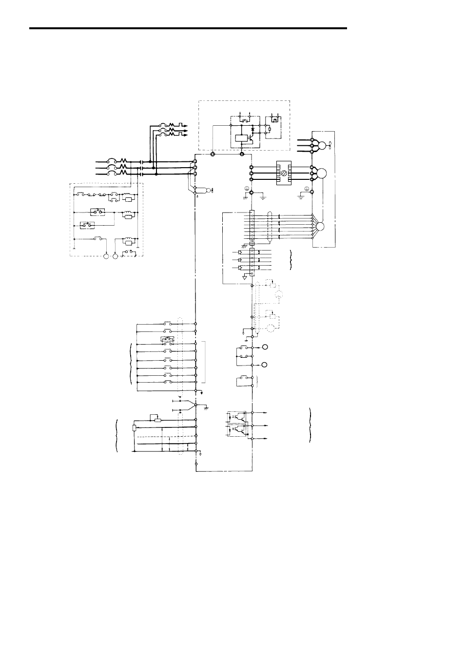
2 connection diagram, Fig. 7 connection diagram Yaskawa Varispeed686SS5 CIMRSSA User Manual
Help with Hobart mixer 115v 1ph, 1/3hp 60hz motor

Pocket bike wiring diagram
DDCSV3.1 3/4Axis CNC Motion Controller 500KHz

Blower Motor Switch Wiring Jeep Cherokee Forum