1 Wire Alternator Wiring Diagram
The wires green/white and white/green are in pins 1 and 2. (assume hooke’s law is obeyed).
Alternator plug harness wiring order??? ClubLexus Lexus Forum Discussion
In this case, pin3 of the 555 timer ic will again become low and the led will be turned on after 10.
1 wire alternator wiring diagram. Therefore, r 1 = 545.4 k ohm. Split loom tubing, 1/2″ diameter 25 feet: The pdf shown here is for a gm.
A load of 4 n causes a certain copper wire to extend by 1.0 mm. At the same time, pins white/brown and brown/white are in pins 7 and 8. Alternator and egr system :
Gm alternator wiring gm alternator wiring. The output and sensor wire (#2) should go to the main power distribution location, as shown, not to the battery. Now, the time is 10 minutes and will be equal to (10 x 60) seconds.
The 4 pin trailer wiring diagram is the most essential thing that you will need to understand. How to wire auto & manual changeover. 4 awg x 5/16 wire lug:
The second connection is the positive (possibly fuseable) terminal and is connected directly to the battery. T= 1.1* r 1 *c 1. The 3 wire alternator wiring diagram is considerably less intrusive than it seems, as only two additional wires are integrated into the rest of the electrical system.
This wire will likely be somewhere in the 12 awg range. Gahi's diagram is the correct way to wire a gm 10si/12si, and utilize all the benefits of that great design. 4.3 out of 5 stars.
In the metal tracks to hold the cb’s tightly) over three busbars which draws hot from each busbar. You will find excellent wiring diagrams for all makes, years and models of vws at vw wiring diagrams. Now, we will see the crossover transmission diagram.
10*60= 1.1*r 1 *1000 μf. Fuel injection wiring diagram (pdf) 1963: It is a type of polyphase system employing three wires (or four including an optional neutral return wire) and is the most common method used by electrical grids worldwide to transfer power.
F α e also f 1 / f 2 = e 1 / e 2 = f 2 = (4 × 3.2) / 1.0 = 12.8 n. A light switch wiring diagram represents a circuit's components and wire connections. Get free android app | download electrical technology app now!
None or up to 60a; The ground wire is connected to the ground rod (see the full setup of earthing and grounding) for safety purposes. The primary charge wire, a third wire that can jump between the regulator and the battery stud, and the exciter wire.
The alternator wiring diagram shows the electricity panels, electrical supply for vehicles, and the battery. Here is an interactive version of our wiring diagram for camper van, skoolie, rv, etc. Most modules use an internal driver to turn the alternator’s field circuit on.
For wire sizes, also see wiring size conversion chart. An alternator is a critical unit in the car's engine. C 1 = 1000 μf.
A 3 wire alternator wiring diagram has three wires: Gm has many different alternators and each has its own alternator wiring diagram and alternator symptoms. Wire sizes on these and most other wiring diagrams are printed on the wire in mm 2.for americans who express wire sizes in gauges, see this wire size conversion table.
The #2 wire ensures the 14.4 or so output is fed to the entire system, eliminating any voltage drop. The following wiring shows an ordinary outlet has been wired and protected through a double pole gfci circuit breaker. This is why you need to know this stuff.
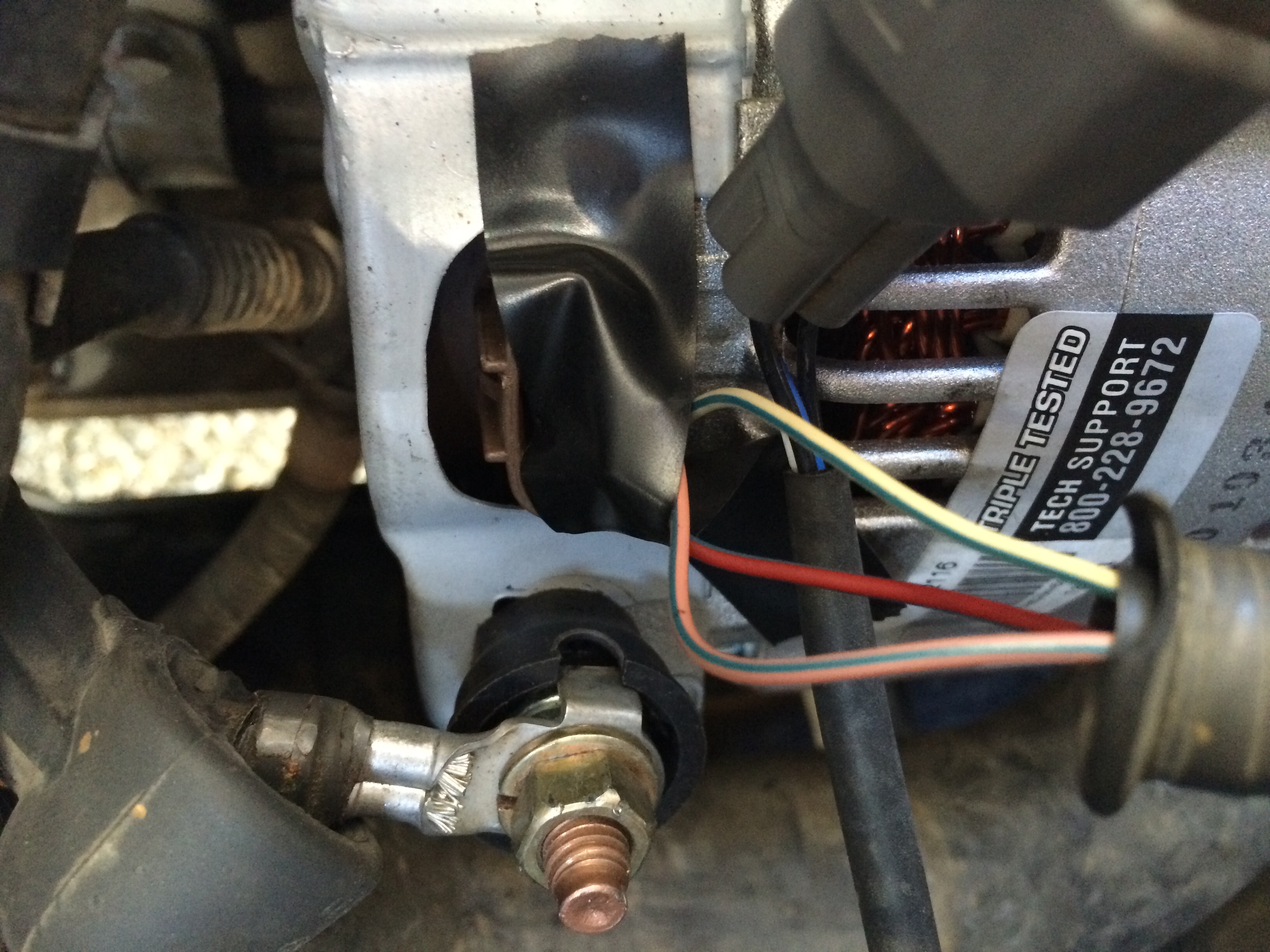
This connection is also called the output connection. And connect the red wire to the output side of the alternator 10/32 stud, take the long wire and connect to the + side of the coil. The orange/white and white/orange wires are in pins 3 and 6.
And we are going to help you out when it comes to this. There are additional two busbars for neutral and ground respectively. See that you have everything you're supposed to have in this kit.
Super beetle only fuel injected. One of the key differences is how the internal voltage regulator determines charge rate. This will either run directly.
It allows power to flow through the alternator and other components of your car. The value of the capacitor will remain same for all the timer circuit. You will likely have a wire charging your oem batteries from the alternator.
Wiring a two poles gfci circuit breaker. Does it check the vehicle’s voltage internally or from an outside source? The alternator turns on the voltage regulator when the engine starts turning the alternator.
Two wire means that you use the main battery wire to the back of the alternator and also ignition wire to the #1 terminal to activate the. This article includes the following subtopics: This wiring diagram is for rv's with factory 30a shore power and will show you what you need to install up to 1200w solar and a 3000w inverter to your existing electrical system.
A body of 200 g was hung from the lower end of a spring which obeys hooke’s law. 2 wire alternator wiring diagram. Find the load that will cause a 3.2 mm extension on the same wire.
Since most cars are running 7 pin connections at the rear end. 4 awg x 1/4 wire lug: Here, wire white/blue and blue/white are in pins 5 and 4.
And also the 4 pin to 7 pin trailer adapter wiring diagram. It usually contains a junction box, an electrical panel, wires, and a light bulb. In crossover transmission, the first end.
30a (campground hookup) or 15a (normal house outlet, via adapter). Three poles, two poles and single pole circuit breakers are used to snap (i.e.
mf35 Massey Harris & Massey Ferguson Forum Yesterday's Tractors
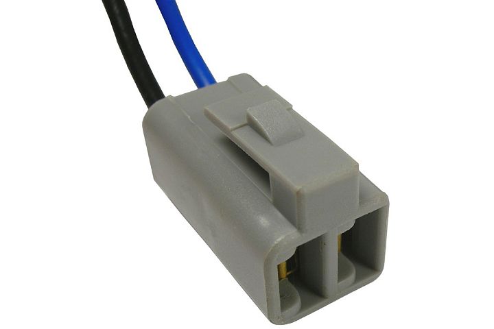
Automotive Pigtails / Sockets
Wiring Diagram & Tutorial for Camper Van Transit, Sprinter, ProMaster, etc. (PDF) FarOutRide

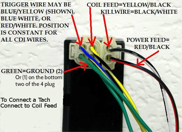
Motorcycle Cdi Ignition Wiring Diagram
Delco Two wire alternator connection issue EType Jaglovers Forums

1971 Alternator/Regulator Wiring Assistance Ford Mustang Forum
Alternator wiring question V8 to 2F (Chev alt to Toyota) IH8MUD Forum